Laser Ignition System | Seminar Report for B.Tech Mechanical Students
Laser Ignition System | Seminar Report for B.Tech Mechanical Students
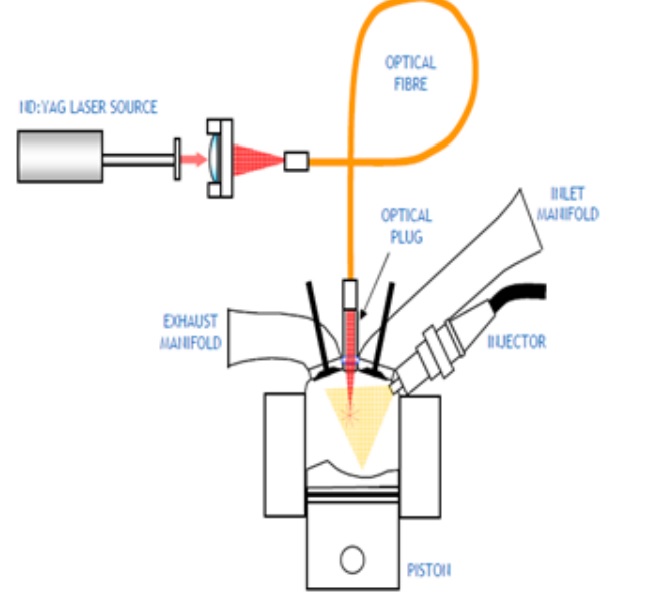
The Laser Ignition System begins with multi-photon ionization of few gas molecules which releases electrons that readily absorb more photons via the inverse bremsstrahlung process to increase their kinetic energy.
Economic as well as environmental constraints demand a further reduction in the fuel consumption and the exhaust emissions of motor vehicles. At the moment, direct Injected fuel engines show the highest potential in reducing fuel consumption and exhaust emissions. Unfortunately, conventional spark plug ignition shows a major disadvantage with modern spray-guided combustion processes since the ignition location cannot be chosen optimally.
It is important that the spark plug electrodes are not hit by the injected fuel because otherwise severe damage will occur. Additionally, the spark plug electrodes can influence the gas flow inside the combustion chamber. It is well know that short and intensive laser pulses are able to produce an ”optical breakdown” in air. Necessary intensities are in the range between 1010- 1011W/cm2.1, 2 at such intensities, gas molecules are dissociated and ionized Within the vicinity of the focal spot of a laser beam and a hot plasma is generated. This Plasma is heated by the incoming laser beam and a strong shock wave occurs. The expanding hot plasma can be used for the ignition of fuel-gas mixtures.
Drawbacks Of Conventional Spark Ignition
Location of spark plug is not flexible as it require shielding of plug from immense heat and fuel spray.
It is not possible to ignite inside the fuel spray.
It require frequent maintenance to remove carbon deposits..
Leaner mixtures cannot be burned.
Degradation of electrodes at high pressure and temperature.
Flame propagation is slow.
Multi point fuel ignition is not feasible.
Higher turbulence levels are required.
What Is Laser?
Lasers provide intense and unidirectional beam of light. Laser light is monochromatic (one specific wavelength). Wavelength of light is determined by amount of energy released when electron drops to lower orbit. Light is coherent; all the photons have same wave fronts that launch to unison. Laser light has tight beam and is strong and concentrated.
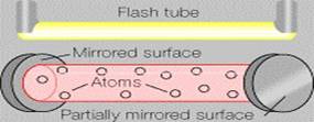
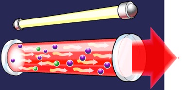
To make these three properties occur takes something called “Stimulated Emission”, in which photon emission is organized. Main parts of laser are power supply, lasing medium and a pair of precisely aligned mirrors. One has totally reflective surface and other is partially reflective (96 %). The most important part of laser apparatus is laser crystal. Most commonly used laser crystal is manmade ruby consisting of aluminum oxide and 0.05% chromium. Crystal rods are round and end surfaces are made reflective.
A laser rod for 3 J is 6 mm in diameter and70 mm in length approximately. Laser rod is excited by xenon filled lamp, which surrounds it. Both are enclosed in highly reflective cylinder, which directs light from flash lamp in to the rod. Chromium atoms are excited to higher energy levels. The excited ions meet photons when they return to normal state. Thus very high energy is obtained in short pulses. Ruby rod becomes less efficient at higher temperatures, so it is continuously cooled with water, air or liquid nitrogen. The Ruby rod is the lasing medium and flashtube pumps it.

Ruby Laser

Laser Induced Spark Ignition
The process begins with multi-photon ionization of few gas molecules which releases electrons that readily absorb more photons via the inverse bremsstrahlung process to increase their kinetic energy. Electrons liberated by this means collide with other molecules and ionize them, leading to an electron avalanche, and breakdown of the gas. Multiphoton absorption processes are usually essential for the initial stage of breakdown because the available photon energy at visible and near IR wavelengths is much smaller than the ionization energy.
For very short pulse duration (few picoseconds) the multiphoton processes alone must provide breakdown, since there is insufficient time for electron-molecule collision to occur. Thus this avalanche of electrons and resultant ions collide with each other producing immense heat hence creating plasma which is sufficiently strong to ignite the fuel. The wavelength of laser depend upon the absorption properties of the laser and the minimum energy required depends upon the number of photons required for producing the electron avalanche.

The minimum ignition energy required for laser ignition is more than that for electric spark ignition because of following reasons: An initial comparison is useful for establishing the model requirements, and for identifying causes of the higher laser MIE. First, the volume of a typical electrical ignition spark is 10^-3 cm3. The focal volume for a typical laser spark is 10^-5 cm3. Since atmospheric air contains _1000 charged particles/cm3, the probability of finding a charged particle in the discharge volume is very low for a laser spark. Second, an electrical discharge is part of an external circuit that controls the power input, which may last milliseconds, although high power input to ignition sparks is usually designed to last <100 ns.
Breakdown and heating of laser sparks depend only on the gas, optical, and laser parameters, while the energy balance of spark discharges depends on the circuit, gas, and electrode characteristics. The efficiency of energy transfer to near-threshold laser sparks is substantially lower than to electrical sparks, so more power is required to heat laser sparks. Another reason is that, energy in the form of photons is wasted before the beam reach the focal point. Hence heating and ionizing the charge present in the path of laser beam. This can also be seen from the propagation of flame which propagates longitudinally along the laser beam. Hence this loss of photons is another reason for higher minimum energy required for laser ignition than that for electric spark.
Advantages
Location of spark plug is flexible as it does not require shielding from immense heat and fuel spray and focal point can be made any where in the combustion chamber from any point It is possible to ignite inside the fuel spray asthere is no physical component at ignition location.
It does not require maintenance to remove carbon deposits because of itself cleaning property.
Leaner mixtures can be burned as fuel ignition inside combustion chamber is also possible here certainty of fuel presence is very high.
High pressure and temperature does not affect the performance allowing the use of high compression ratios.
Flame propagation is fast as multipoint fuel ignition is also possible.
Higher turbulence levels are not required due to above said advantages
Conclusion
1. Laser ignition system allows almost free choice of the ignition location within the combustion chamber, even inside the fuel spray.
2. Significant reductions in fuel consumption as well as reductions of exhaust gases show the potential of the laser ignition process.
3. Minimum ignition energy is mainly determined by the necessary “self-cleaning” mechanism at the beam entrance window from combustion deposits and not by engine related parameters.
4. No differences of the laser ignition process could be found at different laser wavelengths.
5. Laser ignition is nonintrusive in nature; high energy can be rapidly deposited, has limited heat losses, and is capable of multipoint ignition of combustible charges.
References
1] Bergmann and Schaefer, Lehrbuch der Experimental physik: Elektrizit¨at und Magnetismus, vol. 2, Walter de Gruyter Berlin, 1981.
[2]J. Ma, D. Alexander, and D. Poulain, “Laser spark ignition and combustion characteristics of methane-air mixtures,” Combustion and Flame, pp. 492–506, 1998
[3]J. Syage, E. Fournier, R. Rianda, and R. Cohn, “Dynamics of flame propagation using laser-induced spark initiation: Ignition energy measurements,” Journal of Applied Physics, pp. 1499–1507, 1988.
